Iranian Classification Society Rules

< Previous | Contents | Next >
Section 3 Rolled Steels
301. Rolled steels for hull
1. Application
structural
(1) The requirements are to apply to hull structural rolled steels (hereinafter referred to as "steels") not exceeding 100 mm in thickness.
(2) These requirements also apply to normal and higher strength Corrosion Resistant Steels with all
grades up to 50 mm in thickness for steel plates, wide flats, sections and bars when such steel is used as the alternative means of corrosion protection for cargo oil tanks as specified in the performance standard MSC.289 (87) of Regulation 3-11, Part A-1, Chapter II-1 of the SOLAS
Convention (Corrosion protection of cargo oil tanks of crude oil tankers).
strength Corrosion Resistant steels as defined within this requirements, are
Normal and higher
steels whose corro-
sion resistance performance in the bottom or top of the internal cargo oil tank is tested and ap-
proved to satisfy the requirements in MSC.289 (87) in addition to other relevant requirements for hull structural steel, structural strength and construction.
(3) It is not intended that such steels be used for corrosion resistant applications in other areas of a
vessel that are outside of those specified in the performance standard MSC.289 (87) of Regulation 3-11, Part A-1, Chapter II-1 of the SOLAS Convention.
![]()
![]()
(4) Any requirement regarding steels over the thickness specified in Table 2.1.5 is to be left to the discretion of the Society. See Guidance
(5) Where improved through thickness properties are specified for plates and wide flats with thick- ness of 15 mm and over, the tensile test of through thickness property specified in 310. is to be carried out in addition to the requirements of 301.
(6) Steels other than those specified in 301. are to
2.
2. Kinds
Steels are classified as specified in Table 2.1.5.
be in accordance with the requirements of 101.
![]()
![]()
![]()
Table 2.1.5 Grades of Rolled Steels for hull
Kinds | Grade | Thickness (mm) | |
Normal strength steel(1) | Plates(3) | A, B, D , E | 100 |
Sections and bars | 50 | ||
Higher strength steels(2) | Plates(3) | AH 32, D H 32, EH 32, FH 32 AH 36, D H 36, EH 36, FH 36 AH 40, D H 40, EH 40, FH 40 | 100 |
Sections and bars | AH 32, D H 32, EH 32, FH 32 AH 36, D H 36, EH 36, FH 36 AH 40, D H 40, EH 40, FH 40 | 50 | |
NOTE: (1) Provision is made for four grades of normal strength steels based on the impact test requirements. (2) For higher strength steels, provision is made for three strength levels(315, 355 and 390 N mm ) each subdivided into four grades(ex. : AH 32, D H 32, E H 32 and F H 32) based on the impact test temperature. (3) Steel plates include flat bars not less than 600 mm in width. | |||
![]()
![]()
3. Manufacturing process
(1) Where steel plates are manufactured from the continuous casting slabs, the maximum thickness for approval is to be determined, as a rule, with the roll ratio of 6 as standard. However, upon consideration of the manufacturing process, the roll ratio may be reduced to 4 (3 for steel plate thickness in excess of 50 mm).
![]()
(2) The deoxidation practice and chemical composition of each grade are to comply with the re- quirements given in Table 2.1.6. For steel plates and wide flats over 50mm thick and When thermo-mechanical controlled processing (hereinafter referred to as "TMCP") is used as heat
![]()
![]()
treatment, slight deviations in the chemical composition may be allowed Society. See Guidance
4. Heat treatment
as approved by the
The heat treatment of each grade is to comply with the requirements given in Table 2.1.8 and
![]()
![]()
Table 2.1.9. See Guidance
![]()
![]()
![]()
![]()
![]()
![]()
![]()
![]()
![]()
![]()
![]()
![]()
![]()
![]()
Table 2.1.6 Deoxidation Practice and Chemical Composition
Kinds | Grade | Thickness, (mm) | Deoxidation Practice | Chemical Composition ( ) (5) | |||||||||||||
C | Si | Mn | P | S | Cu | Cr | Ni | Mo | Al(8) | Nb | V | Ti | N | ||||
Normal strength steels | A | 50 | Killed and Semi-killed(1) | 0.21 max. (3)(4) | 0.50 max. | 2.5×C min. (4) | 0.035 max. | 0.035 max. | - | - | - | - | - | - | - | - | - |
>50 | Killed | ||||||||||||||||
B | 50 | Killed and Semi-killed | 0.21 max. (4) | 0.35 max. | 0.8 min. (4)(6) | ||||||||||||
>50 | Killed | ||||||||||||||||
D | 25 | Killed | 0.21 max. (4) | 0.35 max. | 0.6 min. (4) | 0.015 min. (2)(9) | |||||||||||
>25 | Fine grain treated(2) | ||||||||||||||||
E | 100 | Killed and Fine grain treated | 0.18 max. (4) | 0.35 max. | 0.7 min. (4) | 0.015 min. (9) | |||||||||||
Higher strength steels (13) | AH 32 | 100 | Killed and Fine grain treated | 0.18 max. | 0.50 max. | 0.90~ 1.60 (7) | 0.035 max. | 0.035 max. | 0.35 max. | 0.20 max. | 0.40 max. | 0.08 max. | 0.015 min. (10) | 0.02~ 0.05 (10)(11) | 0.05~ 0.10 (10)(11) | 0.02 max. (11) | - |
D H 32 | |||||||||||||||||
EH 32 | |||||||||||||||||
AH 36 | |||||||||||||||||
D H 36 | |||||||||||||||||
EH 36 | |||||||||||||||||
AH 40 | 50 | ||||||||||||||||
D H 40 | |||||||||||||||||
EH 40 | |||||||||||||||||
FH 32 | 0.16 max. | 0.90~ 1.60 | 0.025 max. | 0.025 max. | 0.80 max. | 0.009 max. (12) | |||||||||||
FH 36 | |||||||||||||||||
FH 40 | |||||||||||||||||
NOTES: (1) For sections up to 12.5 mm in thickness inclusive, subject to a special approval by the Society, rimmed steel may be accepted. (2) For steels above 25 mm in thickness, aluminium treatment is to be used as a fully killed, fine grain practice. However, killed steel up to 50 mm in thickness may be accepted at the discretion of the Society. (3) For steel sections, maximum carbon content may be increased to 0.23 %. (4) The value of C + Mn/6 is not to exceed 0.40 %. (5) Where additions of any other element have been made as part of the steelmaking practice, the content is to be indicated on the test certificate. (6) When an impact test as killed steels is conducted, the minimum manganese content may be reduced to 0.60 %. (7) For steels up to 12.5 mm in thickness inclusive, the minimum manganese content may be reduced to 0.70 %. (8) Aluminium content is to be represented by the acid soluble aluminium content, but may be determined by the total aluminium content. In such a case, the total aluminium content is not to be less than 0.020 %. (9) Upon the approval by the Society, grain refining elements other than aluminium may be used. (10) The steel is to contain aluminium, niobium, vanadium or other suitable grain refining elements, either singly or in any combination. When used singly, the steel is to contain the specified minimum content of the grain refin- ing element. When used in combination, the specified minimum content of each element is not applicable. (11) The total niobium, vanadium and titanium content is to be less than 0.12 %. (12) If Aluminium is present, the maximum content of nitrogen may be increased to 0.012 %. (13) For TMCP steels, carbon equivalent values(Ceq) and/or cold cracking susceptibility(Pcm) of each steel is to be left to the discretion of the Society. See Guidance | |||||||||||||||||
![]()
![]()
![]()
![]()
![]()
![]()
![]()
![]()
![]()
![]()
![]()
![]()
![]()
![]()
![]()
![]()
Thickness (mm) Grade | 3 | 5 | 5< | 10 | 10< | 15 | 15< | 20 | 20< | 25 | 25< | 30 | 30< | 40 | 40< | 100 | |||
A, B, D , E, A H 32, D H 32, EH 32, F H 32 | 14 | 16 | 17 | 18 | 19 | 20 | 21 | 22 | |||||||||||
A H 36, D H 36, EH 36, F H 36 | 13 | 15 | 16 | 17 | 18 | 19 | 20 | 21 | |||||||||||
A H 40, D H 40, EH40, F H 40 | 12 | 14 | 15 | 16 | 17 | 18 | 19 | 20 | |||||||||||
Table 2.1.7 Mechanical Properties
Grade | Tensile test | Impact test | |||||||||
Yield strength (N m m ) | Tensile strength (N mm ) | Elongation(6) ( (%) | test temp ( ) | Average absorbed energy (1)(J) | |||||||
Thickness, (mm) | |||||||||||
50 | 50 < 70 | 70 < | |||||||||
L(2) | T(2) | L(2) | T(2) | L(2) | T(2) | ||||||
A | 235 min. | 400~520(3) | 22 min. | +20 | - | - | (4) | (4) | (4) | (4) | |
B | 0(5) | 27 min. | 20 min. | 34 min. | 24 min. | 41 min. | 27 min. | ||||
D | -20 | ||||||||||
E | -40 | ||||||||||
AH 32 | 315 min. | 440~570 | 22 min. | 0 | 31 min. | 22 min. | 38 min. | 26 min. | 46 min. | 31 min. | |
D H 32 | -20 | ||||||||||
EH 32 | -40 | ||||||||||
FH 32 | -60 | ||||||||||
AH 36 | 355 min. | 490~630 | 21 min. | 0 | 34 min. | 24 min. | 41 min. | 27 min. | 50 min. | 34 min. | |
D H 36 | -20 | ||||||||||
EH 36 | -40 | ||||||||||
FH 36 | -60 | ||||||||||
AH 40 | 390 min. | 510~660 | 20 min. | 0 | 39 min. | 26 min. | 46 min. | 31 min. | 55 min. | 37 min. | |
D H 40 | -20 | ||||||||||
EH 40 | -40 | ||||||||||
FH 40 | -60 | ||||||||||
NOTE: (1) When the absorbed energy of two or more test specimens among a set of test specimens is less in value than the specified average absorbed energy or when the absorbed energy of a single test specimen is less in value than 70 % of the specified average absorbed energy, the test is considered to be failed. (2) (or T) denotes that the longitudinal axis of the test specimen is arranged parallel (or transverse) to the final direction of rolling. (3) For all thickness of Grade A section, the upper limit of the specified tensile strength, may be exceeded. (4) For Grade A steel over 50 mm in thickness with A R S or C R S heat treatment, impact tests are required. In this case, the average absorbed energy is to comply with the requirements of Grade B steel. (5) For Grade B steels up to 25 mm in thickness, generally no impact testing is required. (6) The minimum elongation for R 1B test specimen (L=200mm) is to be in compliance with the requirement given in the Table below.
| |||||||||||
![]()
Table 2.1.8 Heat Treatment and Size of lot for Impact Test specimen for Normal Strength Steels
Grade | Deoxidation practice | Products(5) | Heat treatment and Size of Lot for Impact Test Specimen(1)(2)(3)(4) | |||||
Thickness(mm) 0 12.5 25 35 50 100 | ||||||||
A | Rimmed(6) | Sections | AR<-> | |||||
Semi-killed | All | AR<-> | ||||||
Killed | Plates | AR<-> | N <-> TM CP<-> CRS<50>(6) ARS<50>(6) | |||||
Sections and bars | AR<-> | |||||||
B | Semi-killed | All | AR <-> | AR<50> | ||||
Killed | Plates | N<50> TM CP<50> CRS<25> ARS<25> | ||||||
Sections and bars | ||||||||
D | Killed | All | AR <50> | TM C P <50> N <50> C R<50> | ||||
Fine grain treated | Plates | AR <50> | TM C P <50> N <50> C R <50> | TM CP<50> N<50> CRS<25> | ||||
Sections and bars | TM C P <50> N <50> C R <50> A R S<50> | |||||||
E | Killed and Fine grain treated | Plates | TM C P < P > N < P > | |||||
Sections and bars | TM C P <50> N <50> CR S<50> AR S<50> | |||||||
NOTES: (1) Indication symbols used in heat treatment are as follows(the same holds henceforth in this Section): A R : As Rolled C R : Controlled Rolling Condition N : Normalized Condition TMCP : Thermo-Mechanical Controlled Processing A R S : As Rolled Condition subject to special approval of the Society CR S : Controlled Rolled Condition subject to special approval of the Society. (2) In the Table, "marks" put at the end of each symbol for heat treatment stand for the volume of each lot. For examples, <50>, <25> and <15> each indicate that steels not greater than 50, 25 and 15 tonnes in weight (belonging to the same charge in the same manufacturing process) are to be taken as one lot; <P>, Piece, indicates that steel material rolled directly from one slab, billet or steel ingot is to be taken as one lot; and <-> indicates that no impact test is required. The term "piece" is understood to mean the rolled product from a single slab, billet or ingot if this is rolled directly into plates, sections or bars. (3) TM CP, N or C R may be applied to instead of being left in a state of AR. In this case, steels are to be treated equivalent to those left in a state of A R with regard to the fundamental unit of lot. (4) Steel plates include flat bars not less than 600 mm in width. (5) For sections up to 12.5 mm in thickness, subject to a special approval by the Society, rimmed steel may be accepted. (6) See Note (4) of Table 2.1.7 | ||||||||
![]()
Table 2.1.9 Heat Treatment and Size of Lot for Impact Test Specimen for Higher Strength Steels
Grade | Deoxidation practice | Products(5) | Heat treatment and Size of Lot for Impact Test Specimen(1)(2)(3)(4) | ||||||
Thickness (mm) 0 12.5 20 25 35 50 100 | |||||||||
AH 32 AH 36 | Killed and Fine grain treated | Nb and/or V(5) | Plates | AR<50> | TMCP<50> N<50> CR<50> | TMCP<50> N<50> CR<25> | |||
Sections and bars | TM CP<50> N<50> CR<50> ARS<25> | ||||||||
Al alone or with Ti | Plates | AR<50> | ARS<50> | ||||||
TM CP<50> N<50> C R<50> | TMCP<50> N<50> CR<25> | ||||||||
Sections and bars | TM CP<50> N<50> CR<50> ARS<25> | ||||||||
D H 32 D H 36 | Nb and/or V(5) | Plates | AR<50> | TMCP<50> N<50> CR<50> | TMCP<50> N<50> CR<25> | ||||
Sections and bars | TMCP<50> N<50> CR<50> ARS<25> | ||||||||
Al alone or with Ti | Plates | AR<50> | ARS <25> | ||||||
TM CP<50> N<50> C R<50> | TM C P<50> N<50> CRS<25> | ||||||||
Sections and bars | TM CP<50> N<50> CR<50> ARS<25> | ||||||||
EH 32 EH 36 | Any grain refining treated elements | Plates | TM CP<P> N<P> | ||||||
Sections and bars | TM CP<25> N<25> C R<15> ARS<15> | ||||||||
FH 32 FH 36 | Plates | TMCP<P> N<P> Q T<P> | |||||||
Sections and bars | TM CP<25> N<25> Q T<25> ARS<15> | ||||||||
AH 40 | Plates | AR<50> | TMCP<50> N<50> CR<50> | TM CP<50> N<50> Q T<P> | |||||
Sections and bars | AR<50> | TMCP<50> N<50> CR<50> | |||||||
DH 40 | Plates | TM CP<50> N<50> CR<50> | TM CP<50> N<50> Q T<P> | ||||||
Sections and bars | TM CP<50> N<50> CR<50> | ||||||||
EH 40 | Plates | TMCP<P> N<P> Q T<P> | |||||||
Sections and bars | TM CP<25> N<25> Q T<25> | ||||||||
FH 40 | Plates | TMCP<P> N<P> Q T<P> | |||||||
Sections and bars | TM CP<25> N<25> Q T<25> | ||||||||
NOTES: (1) Indication symbols used in heat treatment are as follows (the same holds henceforth in this Section); A R : As rolled C R : Controlled Rolling Condition N : Normalized Condition TM CP : Thermo-Mechanical Controlled Processing Q T : Quenched and Tempered Condition A R S : As Rolled Condition subject to special approval of the Society CR S : Controlled Rolled Condition subject to special approval of the Society. (2) In the Table, "marks" put at the end of each symbol for heat treatment stand for the volume of each lot. For ex- amples, <50>, <25> and <15> each indicate that steels not greater than 50, 25 and 15 tonnes in weight (belonging to the same charge in the same manufacturing process) are to be taken as one lot; <P>, Piece, indicates that steel material rolled directly from one slab, billet or steel ingot is to be taken as one lot; and <-> indicates that no im- pact test is required. The term "piece" is understood to mean the rolled product from a single slab, billet or ingot if this is rolled directly into plates, sections or bars. (3) TM C P , N or C R may be applied to instead of being left in a state of A R . In this case, steels are to be treated equivalent to those left in a state of A R with regard to the fundamental unit of lot. (4) Steel plates include flat bars not less than 600 mm in width. (5) Niobium treatment stands for the addition of N b either singly or in any combination, regardless of the Nb content, for grain refining. (Refer to Note (10) of Table 2.1.6) | |||||||||
![]()
5. Mechanical properties
The mechanical properties of steels are to comply with the requirements given in Table 2.1.7.
6. Selection of test samples
(1) All material in a batch presented for acceptance tests is to be of the same product form e.g. plates, flats, sections, etc. from the same cast and in the same condition of supply. The test samples are to be fully representative of the material and, where appropriate, are not to be cut from the material until heat treatment has been completed.
(2) For the samples of steel from which tensile test specimens are cut, except where specially ap-
proved by the Society, steels not greater than 50 tonnes in mass (where the amount of scatter is to be less than 10 mm in thickness or diameter even when they belong to the same cast in
the same manufacturing process) are to be treated as one lot, and the largest one in thickness
or diameter is to be selected from each lot.
![]()
![]()
(3) For the samples of steel from which impact test specimens are cut, unless otherwise specially provided or except where specially approved by the Society, the thickest test sample is to be selected from each lot specified in Table 2.1.8 and Table 2.1.9, according to the substance of deoxidation practices, type of products and kind of heat treatments. See Guidance
(4) The test samples are to be taken from the following portions according to the requirements (a) to (c) below and Fig 2.1.4, unless otherwise specified:
(a) Plates and flat bars wider than 600 mm :
One end at a portion approximately 1/4 of the width from the flange end of the plates or flat bars.
(b)
(c)
Sections and flat bars not exceeding 600 mm in width:
One end at a portion approximately 1/3 of the width from the flange end. In case of channels, bulb plates and H-section, the test samples may be taken from the portion approx- imately 1/4 of the depth from the centre line of the web.
Bars:
The test samples are to be taken so that the axis of each test specimen may lie as near as possible to the portion specified in (i) and (ii) below. This rule, however, does not apply when, because dimensions of cross section are insufficient for standard test specimens, a piece cut in a proper length from the product having the largest diameter of a certain lot is used as it is for a tensile test.
(i) For non-circular sections, at approximately 1/6 of the largest distance from the outside.
(ii) For circular section, at approximately 1/6 of the diameter from the outside.
7. Selection of test specimens
(1) Test specimens are not to be heat treated separately from the product.
(2) Tensile test specimens are to be taken according to (a) to (c) below.
(a) One test specimen is to be taken from one test sample.
(b) The test specimens are to be taken with their longitudinal axis normal to the final direction
of rolling. For sections, bars and flat bars not exceeding 600 mm in width or when cially approved by the Society, however, they are to be taken with their longitudinal
![]()
parallel to the final direction of rolling.
spe- axis
![]()
(c) Flat test specimens of full product thickness are, generally, to be used. Round test specimen may be used when the plates and shapes(except bars) thickness exceeds 40 mm or for bars. When tensile test specimens of bar type are taken from plates and shapes except bars, they are to be taken at a portion approximately 1/4 of the thickness from the surface.
(3) Impact test specimens are to be taken according to (a) to (c) below.
(a)
(b)
(c)
A set of test specimens is to be taken from one test sample.
The test specimens are to be taken with their longitudinal axis parallel (L direction) to the final direction of rolling. When deemed necessary by the Society, however, they are to be taken with their longitudinal axis normal (T direction) to the final direction of rolling.
When the product thickness does not exceed 40 mm, the test specimens are to be cut with
their edge within 2 mm from the "as rolled" surface. When the product thickness exceeds 40 mm, the test specimen is to be taken at a portion where the axis of the test specimen cor- responds to approximately 1/4 of the thickness (1/6 of the diameter of bars) from the surface.
![]()
![]()
8. Surface inspection and verification of dimensions See Guidance
(1) Scope
(a) The Requirements apply to the tolerance on thickness of steel plates and wide flats with
widths of 600 mm or greater with thicknesses of 5 mm and over. The thickness tolerances for products below 5 mm may be specially agreed by the Society.
(b) Where Class C of ISO 7452 is applied in lieu of (a) above, the requirements in (4) and (5) below may not be applied. If Class C of ISO 7452 is to be used, the portion of the foot- note of ISO 7452, Table 2, which reads “Also a minus side of thickness of 0.3 mm is permitted.” is not to be applied.
(c)
(d)
Tolerances for length, width and flatness should be in accordance with a recognized national or international standard which specially agreed by the Society.
Tolerances for rolled steel other than plates and wide flats may be specially agreed.
(2) Responsibility
(a) The responsibility for verification and maintenance of the steel plates within the required tol- erances rests with the manufacturer. The Surveyor may require to witness some
measurements.
(b) The responsibility for storage and maintenance of the delivered steel plates with acceptable
level of surface conditions rests with the shipyard before the steel plates are used in fabrication.
(3)
(4)
(5)
Thickness tolerances
(a) The tolerances on thickness of a given steel plates are defined as:
(i) Minus tolerance is the lower limit of the acceptable range below the nominal thickness.
(ii) Plus tolerance is the upper limit of the acceptable range above the nominal thickness.
(iii) Nominal thickness is defined by the purchaser at the time of enquiry and order.
(b) The minus tolerance on thickness of products is 0.3 mm irrespective of nominal thickness.
(c) The plus tolerances on nominal thickness are to be in accordance with a recognized national
or international standard which specially agreed by the Society.
(d) The tolerances on nominal thickness are not applicable to areas repaired by grinding which are to be in accordance with the requirements in 301. 9. (3) of the Rules.
Average thickness
(a) The average thickness of steel plates or piece is defined as the arithmetic mean of the measurements made in accordance with the requirements in (5) below.
(b) The average thickness of steel plates or piece is not to be less than the nominal thickness.
Thickness measurements
(a) At least two lines among Line 1, Line 2 or Line 3 as shown in Fig. 2.1.4-1, are to be se- lected for the thickness measurements and at least three points on each selected line as shown in Fig. 2.1.4-1 are to be selected for thickness measurement. Automated method or manual method is applied to the thickness measurements.
(b) For automated methods, the measuring points at sides are to be located not less than 10
mm but not greater than 300 mm from the transverse or longitudinal edges
plates. For manual methods, the measuring points at sides are to be located not
of the steel
less than 10
mm but not greater than 100 mm from the transverse or longitudinal edges of the steel
plate.
![]()
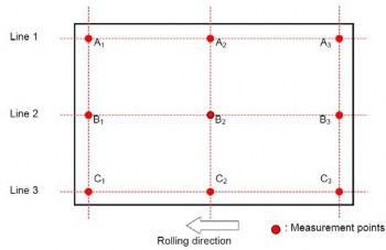
Fig 2.1.4-1 Locations of Thickness Measuring Points
(c) If more than three points are taken on each line the number of points each line.
shall be equal on
(d)
Where the plate is to be later cut by the manufacturer as shown in Fig
urement locations to be same as the requirements in (a) thru (c) above.
2.1.4-2, the meas-
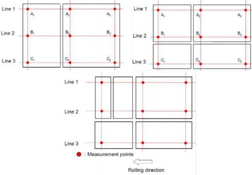
Fig 2.1.4-2 Locations of Thickness Measuring Points for Cut Steel Plates
(e) The procedure and the records of measurements are to be made available to and copies provided on request.
9. Quality and repair of defects
the Surveyor
(1) The quality of finished steel is to be in accordance with the requirements specified in 101. 1.
and 2. The steel is to be reasonably free from segregations and non-metallic inclusions.
(2) If plates and wide flats are ordered with ultrasonic inspection or required by the Society, the test procedure and acceptance criteria are to be made in accordance with an accepted standard at the discretion of the Society. However, the probe frequency is to be of 4MHz in general.
![]()
![]()
See Guidance
![]()
![]()
(3) The surface defects may be removed by local grinding. However, the procedure of removal of defect and repair is to be in accordance with the Guidance relating to the Rules specified by the Society. See Guidance![]()
10. Retest Procedures
(1) Where the tensile test fails to meet the requirements, two further tensile tests may be made from the same piece. If both of these additional tests meet all of the requirements, the piece and the remaining pieces from the same lot may be accepted.
(2) If one or both of the additional tests referred to above are unsatisfactory, the piece from which
the above-mentioned test pieces have been taken is to be rejected. However, the remaining ma- terial from the same lot may be accepted, provided that two of the remaining pieces in the lot, selected in the same way, are tested with satisfactory results.
(3) (a) Where the result of the impact test is unsatisfactory, additional tests may be carried out, with the exception of the cases specified in (i) and (ii) below, by taking a set of test speci- mens out of the same piece from which the above-mentioned test specimens have been taken.
(i) The absorbed energy of all test specimens is under the required average absorbed energy.
(ii) The absorbed energy of two of the test specimens is under 70 % the required average absorbed energy.
(b) In case of the previous (a), all pieces of the same lot from which the test specimens have been taken, may be accepted, provided that the average absorbed energy of the six test specimens, including those which have been rejected as unsatisfactory, is not less than the required average absorbed energy, and that not more than two individual results are lower than the required average absorbed energy and of these, not more than one result is below 70 % of the required average absorbed energy.
(4) When the initial piece, representing a lot, gives unsatisfactory results from the additional Charpy
V-notch impact tests referred to the preceding (3), this piece is to be rejected but the remaining material in the lot may be accepted provided that two of the remaining pieces in the lot are tested with satisfactory results. If unsatisfactory results are obtained from either of these two pieces, then the lot of material is to be rejected. The pieces selected for these additional tests are to be the thickest remaining in the batch.
(5) If any test specimen fails because of faulty preparation, visible defects or (in the case of tensile test) because of fracturing outside the range permitted for the appropriate gauge length, the de- fective test piece may, at the Surveyors discretion, be disregarded and replayed by an additional test piece of the same type.
(6) Where the test pieces fail in the retests specified above, the piece from which the test pieces have been taken is to be rejected, However, at the consultation of the manufacturer and the or- derer, the remaining pieces in the lot may be resubmitted individually for test and those pieces which give satisfactory results may be accepted.
(7) At the consultation of the manufacturer and the order, the rejected piece may be resubmitted af- ter heat treatment of re-heat treatment, or may be resubmitted as any other grade of steel and then, may be accepted, provided that the required tests are satisfactory.
11. Marking
(1) Steels which have satisfactorily complied with the required tests are to be marked with the identification mark in accordance with the requirements in 110.
(2) Materials supplied in the thermo-mechanical controlled processing condition is to have the letters
TM added after the material grade mark. (e.g. E H 40TM )
(3) Steel plates that have complied with the requirements for corrosion resistant steel will be
marked with a designation by adding a corrosion designation to the unified identification mark for the grade of steel. And the corrosion resistant steel is to be designated according to its area of application as follows:
(a) Lower surface of strength deck and surrounding structures : RCU
(b) Upper surface of inner bottom plating and surrounding structures : RCB
(c) For both strength deck and inner bottom plating : RCW
(e.g. AH32 TM RCU Z35)
![]()
12. Forming
![]()
![]()
The cold deformation limit of hull structural rolled steels is to be in accordance with the Guidance specially specified by the Society. See Guidance
302. Rolled steel plates for boiler
1. Application
(1) These requirements are to apply to the steel plates (hereinafter referred to as "steel plates") for boilers and pressure vessels to be used at high temperatures.
(2) Steel plates other than those specified in 302. are to comply with the requirements in 101. 2.
2. Kinds The steel plates are classified as specified in Table 2.1.10.
![]()
Table 2.1.10 Grades of Steel Plates
Grade | Thickness (mm) | ||
RSP 42, | RSP 46 | 6 | 200 |
RSP 49 | |||
RSP 46A, | RSP 49A | 6 | 150 |
![]()
3. Heat treatment
(1) For steel plates of the "R SP 42, R SP 46 and R SP 49" grade with 50 mm or less and of the "R SP 46A and R SP 49A " grade with 38 mm or less in thickness, they are to be as rolled. They, how- ever, may be heat treated(normalized or annealed for stress relieving) as deemed necessary by the manufacturer.
(2) For steel plates of the "R SP 42, R SP 46 and R SP 49" grade more than 50 mm and of the "R SP
46A
tain that
and R SP 49A " grade more than 38 mm in thickness, they are to be either normalized to ob- the normal grain size or heated uniformly to such a temperature at the time of hot forming an effect equivalent to normalizing can be achieved. In case of normalizing, it is, in prin-
ciple, to be performed by the manufacturer.
4. Chemical composition
The chemical composition of steel
2.1.11.
![]()
![]()
![]()
Table 2.1.11 Chemical Composition
plates is to comply with the requirements given in Table
Grade | Chemical composition (%) | |||||||
Thickness t (mm) | C | Si | Mn | P | S | Mo | ||
RSP 42 | t 25 25 < t 50 50 < t 200 | 0.24 max. 0.27 max. 0.30 max. | 0.15 0.40 | 0.90 max. | 0.030 max. | 0.030 max. | - | |
RSP 46 | t 25 25 < t 50 50 < t 200 | 0.28 max. 0.31 max. 0.33 max. | ||||||
RSP 49 | t 25 25 < t 50 50 < t 200 | 0.31 max. 0.33 max. 0.35 max. | 1.20 max. | |||||
RSP 46A | t 25 25 < t 50 50 < t 100 100 < t 150 | 0.18 max. 0.21 max. 0.23 max. 0.25 max. | 0.90 max. | 0.45~0.60 | ||||
RSP 49A | t 25 25 < t 50 50 < t 100 100 < t 150 | 0.20 max. 0.23 max. 0.25 max. 0.27 max. | ||||||
NOTES: 1. For R SP 46 with 25 mm and over in thickness, carbon and manganese content may be 0.30 % or less and 1.00 % or less, respectively. | ||||||||
![]()
5. Mechanical properties
The mechanical properties of steel plates are to comply with the requirements given in Table 2.1.12.
![]()
![]()
6. Selection and heat treatment of test samples See Guidance
(1) For the steel plates which are not to be heat treated, one test sample is to be taken from each plate as rolled directly from one slab or ingot
(2) For the steel plates which are to be heat treated, one test sample is to be taken from every similarly heat treated plate as rolled directly from one slab or ingot.
(3) For steel plates to which stress relieving is required after welding or stress relieving is applied
![]()
![]()
by the purchaser one or several times repeatedly during their working process, instruction of that effect is to be given at the time when they are placed for an order. In case where the pforor ctehdeurteesot f sastmrepslsesrebliyevhinegatiinsgntohtemspescliofiwedly bayndtheunpifuorrcmhalysert,o athheeattemtrpeeartmatuenret iosf t6o00be aptopli6ed5
![]()
0 , holding at that temperature for a period of over one hour per 25 mm of thickness, and
then, to be cooled to 300 in the furnace before exposure in a still atmosphere.
(4) The test samples are to be taken end of the plates.
![]()
![]()
![]()
![]()
Table 2.1.12 Mechanical Properties
from the portion approximately 1/4 of the width from the side
Grade | Yield strength (N mm ) | Tensile strength (N mm ) | Elongation (%) | |
R 1A | R 10 | |||
RSP 42 RSP 46 RSP 49 | 225 min. 245 min. 265 min. | 410 ~ 550 450 ~ 590 480 ~ 620 | 21 min. 19 min. 17 min. | 25 min. 23 min. 21 min. |
RSP 46A RSP 49A | 255 min. 275 min. | 450 ~ 590 480 ~ 620 | 19 min. 17 min. | 23 min. 21 min. |
NOTE: (1) R 1A tensile test specimen is to be used for steel plate up to 50mm in thickness and R 10 test specimen for steel plate more than 50 mm in thickness. However R 10 test specimen can be used for steel plate more than 40 mm in thickness. (2) For material under 8 mm in thickness, a deduction from the specified percentage of elongation of 1 % is to be made for each decrease of 1 mm of the specified thickness. (3) For the plates over 90 mm in thickness, the elongation may be reduced from that mentioned in the above Table by 0.5 % for each increment of 12.5 mm or fraction thereof exceeding 90 mm in thickness. Such reduction, however, is limited to 3 %. (4) In case where the elongation of R SP 46A with thickness between 6mm and 20 mm exclusive and R SP 49A steel plate is insufficient within 3 % of the specified value, It will be able to regard as satisfactory if the elongation of the gauge length 50 mm which includes a rupture part is of 25 % or more. | ||||
7. Selection of test specimens
Tensile test specimens are to be taken according to (1) to (3) below.
(1) One test specimen is to be taken from one test sample.
(2) The test specimens are to be taken with their longitudinal axis normal rolling.
to the final direction of
(3) The test specimens of bar type are to be taken from the portion approximately 1/4 of the thick-
ness from the surface.
8. Tolerance for thickness
Surface inspection and verification of dimensions are to be in accordance with the requirements in
301. 8. The minus tolerance for the nominal thickness of plates is to be 0.25 mm.
9. Retest procedure
Where the tensile tests from the first test specimens selected fail to meet the requirements, addi- tional tests may be conducted according to the requirements given in 109.
10. Marking
(1) Steel plates which have satisfactorily complied with the required tests are to be marked with the identification mark relating to heat treatment in addition to the requirements in 110.
![]()
(2) The marks relating to heat treatment are to be as specified in the following:
(a) Where the plates are normalized : N (e.g. : RSP 46N)
(b) Where the test specimens are normalized : TN (e.g. : RSP 46TN)
(c) Where the test specimens are heat treated corresponding to the stress relieving to be applied
: SR (e.g. : RSP 46N-SR, RSP 46TN-SR)
303. Rolled steel plates for pressure vessel
1. Application
(1) These requirements are mainly to apply to the steel plates for pressure vessels to be used at at- mospheric temperature (hereinafter referred to as "steel plates")
(2) The steel plates having characteristics differing from those specified in 303. are to comply with the requirements in 101. 2.
2. Kinds
The steel plates are classified as specified in Table 2.1.13.
Table 2.1.13 Grades of Steel Plates
Grade | Thickness (mm) | |
RPV 24 | 6 | 200 |
RPV 32, RPV 36, RPV 42, RPV 46, RPV 50 | 6 | 150 |
![]()
3. Heat treatment
(1) RP V 24 plate is to be as rolled. The plates, however, may be normalized as deemed necessary by the Society.
(2) RP V 32 and RP V 36 plates are to be as rolled. The plates, however, may be normalized as
deemed necessary by the Society. But, they may be T M C P or quenched and tempered under the approval by the Society.
(3) RP V 42 plate is to be TM C P . The plate, however, may be normalized or quenched and tem- pered under the approval by the Society.
(4) RP V 46 and RP V 50 plates are to be quenched
the approval by the Society.
4. Chemical composition
and tempered. But, they may be TM CP under
(1) The chemical composition of
2.1.14.
![]()
![]()
![]()
![]()
![]()
![]()
Table 2.1.14 Chemical Composition
steel plates is to comply with the requirements given in Table
Grade | Chemical composition ( ) | Carbon equivalent ( ) | ||||||
C | Si | Mn | P | S | 50(mm) | 50 < 75(mm) | ||
RPV 24 | 100 mm | 0.18 max. | 0.35 max. | 1.40 max. | 0.030 max. | 0.030 max. | - | - |
> 100 mm | 0.20 max. | |||||||
RPV 32 | 0.18 max. | 0.55 max. | 1.60 max. | - | - | |||
RPV 36 | 0.20 max. | - | - | |||||
RPV 42 | 0.18 max. | 0.75 max. | 1.44 max. | 0.46 max. | ||||
RPV 46 | ||||||||
RPV 50 | 1.45 max. | 0.47 max. | ||||||
NOTE: (1) Where deemed necessary, other elements than specified in Table 2.1.14 may be added. In that case, such elements are to be stated in the test sheets. (2) For R PV 46 and R P V 50 steel plates which not to be quenched and tempered, slight deviations in the chemical composition may be allowed as approved by the Society. | ||||||||
![]()
(2) Carbon equivalent(Ceq) and weld cold cracking susceptibility(Pcm) comply with the requirements given in Table 2.1.14-1.
![]()
![]()
![]()
![]()
![]()
![]()
![]()
![]()
![]()
Table 2.1.14-1 Carbon equivalent(Ceq) and Pcm value
value of steel plates are to
Grade | Heat treatment | Carbon equivalent (%) | Pcm value (%) | |||||||
50 (mm) | 50 < 75 (mm) | 75 < 100 (mm) | 100 < 125 (mm) | 125 < 150 (mm) | 50 (mm) | 50 < 75 (mm) | 75 < 100 (mm) | 100 < 150 (mm) | ||
R PV 32 | TMCP(1) | 0.39 max. | 0.41 max. | 0.43 max. | 0.24 max. | 0.26 max. | 0.28 max. | |||
R PV 36 | 0.40 max. | 0.42 max. | 0.44 max. | 0.26 max. | 0.27 max. | 0.29 max. | ||||
R PV 42 | 0.43 max. | 0.45 max. | - | 0.27 max. | 0.28 max. | 0.29 max. | - | |||
R PV 46 | Quenching and Tempering(2) | 0.44 max. | 0.46 max. | 0.49 max. | 0.52 max. | 0.54 max. | 0.28 max. | 0.30 max. | ||
R PV 50 | 0.45 max. | 0.47 max. | 0.50 max. | 0.53 max. | 0.55 max. | |||||
(Note) (1) Carbon equivalent and Pcm value of R P V 32, R P V 36 and RP V 42 plates quenched and tempered are to be as deemed appropriate by the Society. See Guidance (2) Carbon equivalent and Pcm value of R P V 46 and R PV 50 plates, which not to be quenched and tempered, are to be as deemed appropriate by the Society. See Guidance | ||||||||||
![]()
![]()
![]()
![]()
5. Mechanical properties
The mechanical properties of steel
2.1.15.
plates are to comply with the requirements given in Table
![]()
![]()
![]()
![]()
![]()
![]()
![]()
![]()
![]()
![]()
![]()
![]()
![]()
![]()
![]()
![]()
![]()
![]()
Table 2.1.15 Mechanical Properties
Grade | Tensile test | Impact test | ||||||||
Yield strength (N mm ) | Tensile strength (N mm ) | Elongation( ) | Test temp. ( )(5) | Average absorbed energy(J) | Absorbed energy of individual test specimen(J) | |||||
Thickness of plate t (mm) | Thickness of plate t (mm) | |||||||||
50 | 50< 100 | 100< 200 | 16(2) | 16< 40(2) | 40< | |||||
RP V 24 | 235 min. | 215 min. | 195 min. | 400 510 | 17 min. | 21 min. | 24 min. | 0 | 47 min. | 27 min. |
RP V 32 | 315 min. | 290 min. | 275 min.(1) | 490 610 | 16 min. | 20 min. | 23 min. | |||
RP V 36 | 355 min. | 335 min. | 315 min.(1) | 520 640 | 14 min. | 18 min. | 21 min. | |||
RP V 42 | 410 min. | 390 min. | 370 min.(1) | 550 670 | 12 min. | 16 min. | 18 min. | -10 | ||
RP V 46 | 450 min. | 430 min. | 410 min.(1) | 570 700 | 19 min.(4) | 26 min.(4) | 20 min. | |||
RP V 50 | 490 min. | 470 min. | 450 min.(1) | 610 740 | 18 min.(4) | 25 min.(4) | 19 min. | |||
NOTE: (1) To be applied for the plates 150 mm or less in thickness (2) To be tested with R 1A test specimen. (3) To be tested with R 1A test specimen. When the capacity of the available testing machine does not permit test- ing the full thickness specimen, R 4 test specimen may be used. (4) To be tested with R 5 test specimen. (5) Test temperature of R P V 32, RP V 36 and RPV 42 plates manufactured by TM CP is to be -20 . | ||||||||||
![]()
![]()
![]()
6. Selection of test samples See Guidance
(1) For the steel plates which are not to be heat treated, one test sample is to be taken from each plate as rolled directly from one slab or ingot.
(2) For the steel plates which are to be heat treated, one test sample is to be taken from every similarly heat treated plate as rolled directly from one slab or ingot.
(3) For steel plates to which stress relieving is required after welding or stress relieving is applied
by the purchaser, test samples are to be heat treated in accordance with the requirements in
302. 6 (3)
(4) The test samples are to be taken from the portion approximately 1/4 of the width from the side end of the plate.
7. Selection of test specimen
(1) Tensile test specimens are to be taken according to (a) to (c) below.
(a)
(b)
(c)
One test specimen is to be taken from one test sample.
The test specimens are to be taken with their longitudinal axis normal to the final direction of rolling .
The test specimens of bar type are to be taken from the portion approximately 1/4 of the thickness from the surface.
![]()
![]()
(2) Impact test specimens is to be taken according to (a) to (c) below. See Guidance
(a)
(b)
(c)
A set of test specimens are to be taken from one test sample.
The test specimens are to be taken with their longitudinal axis parallel (L direction) to the final direction of rolling. Where deemed necessary by the Society, however, they are to be taken with their longitudinal axis normal (T direction) to the final direction of rolling.
The test specimens are to be taken at a portion where the axis of the test specimen corre-
sponds to approximately 1/4 of the thickness from the surface.
8. Tolerance for thickness
Surface inspection and verification of dimensions are to be in accordance with the requirements in
301. 8. The minus tolerance for the nominal thickness of plates is to be 0.25 mm.
9. Retest procedures
Where the tensile test and impact tests from the first test specimen selected fails to meet the re- quirements, additional tests may be conducted according to the requirements given in 109.
10. Marking
(1) Steel plates which have satisfactorily complied with the required tests are to be marked with the identification mark relating to heat treatment in addition to the requirements in 110.
(2) The marks relating to heat treatment in (1) are to be as specified in the following:
(a) Where the plates are normalized : N (e.g. : R PV 32N)
(b) Where the plates are quenched and tempered : Q T (e.g. : R P V 46Q T)
(c) Where the plates are heat treated in TM CP condition : TM (e.g. : R P V 36TM )
(d) Where only test specimens are normalized in the steel plate as rolled) : TN (e.g. : R P V
32TN)
(e) Where the test specimens are heat treated corresponding to the stress relieving to be applied in the steel plate normalized : N SR (e.g. : R PV 32N SR)
11. Steel plates equivalent to standard
(1) The mild steel plates of grade R D and RE , the high tensile steels of rolled steels for hull speci- fied in 301. are taken as equivalent to the plates specified in 303. in case where the test specimens are taken as required in Pars 6 and 7 and test results comply with the requirements in 301. In this case, "P V " is to be suffixed to the markings to indicate the kind of plates specified in 301.
![]()
(2) Any requirements regarding heat treatment of steel plates specified in (1) is left to the dis- cretion of the Society.
![]()
304. Rolled steels for low temperature service
1. Application
(1) The requirements are to apply to the rolled steels not exceeding 40 mm in thickness intended
for tanks and ship's hull structures adjacent to tanks
such a hull structures of refrigerated cargo carrier (hereinafter referred to as "steels").
![]()
![]()
(2) Any requirement regarding the steels over 40 mm in Society. See Guidance
of liquefied gas carriers, and other parts which are exposed to low temperature
thickness is left to the discretion of the
(3) The requirements other than those specified in 304. are applicable to the requirements in 301.
(4) The steels other than those specified in 304. are
2. Kinds
Steels are classified as specified in Table 2.1.16.
Table 2.1.16 Grades and Chemical Composition
to comply with the requirements in 101. 2.
Grade | Deoxidation | Chemical composition (%) | ||||||
C | Si | Mn | P | S | Ni | |||
RL 235A | Fully killed Aluminium treated fine grain | 0.15 max. | 0.15~0.30 | 0.70~1.50 | 0.035 max. | 0.035 max. | 0.8 max. | |
RL 235B | ||||||||
RL 325A | 0.16 max. | 0.15~0.50 | 0.80~1.60 | |||||
RL 325B | ||||||||
RL 360 | 1.16 max. | 0.15~0.50 | 0.80~1.60 | |||||
RL 2N255 | 1.17 max. | 0.30 max. | 0.70 max. | 0.025 max. | 0.025 max. | 2.10~2.50 | ||
RL 3N255 | 0.15 max. | 3.25~3.75 | ||||||
RL 3N275 | 0.17 max. | |||||||
RL 3N440 | 0.15 max. | |||||||
RL 5N590 | 0.13 max. | 1.50 max. | 4.75~6.00 | |||||
RL 9N520 | 0.12 max. | 0.90 max. | 8.50~9.50 | |||||
RL 9N590 | 0.12 max. | |||||||
3. Heat treatment
![]()
The heat treatment of steels is to comply with the requirements given in Table 2.1.17.
![]()
Table 2.1.17 Heat Treatment
grade | Heat treatment |
RL 235A | Normalized or TM CP |
RL 235B | |
RL 325A | |
RL 325B | Quenched and Tempered or TM CP |
RL 360 | |
RL 2N255 | Normalized or Quenched and Tempered(1) |
RL 3N255 | |
RL 3N275 | |
RL 3N440 | Quenched and Tempered(1) |
RL 5N590 | |
RL 9N520 | Double normalized and tempered(1) |
RL 9N590 | Quenched and tempered(1) |
NOTE: (1) Heat treatment may be conducted according to TM CP , subject to the special approval by the Society. | |
4. Deoxidation practice and chemical composition
(1) The deoxidation practice and chemical composition of each grade are to comply with the re- quirements given in Table 2.1.16. When deemed necessary, chemical elements other than those given in the table may be added.
(2) When heat treatment has been conducted according to T M C P , the chemical composition of steels specified in Table 2.1.16 may be modified subject to the approval by the Society.
5. Mechanical properties
The mechanical Where deemed additionally.
properties of steels are to comply with the requirements given in Table 2.1.17-1.
necessary by the Society. other tests on notch toughness may be required
![]()
![]()
![]()
![]()
![]()
![]()
![]()
![]()
![]()
![]()
![]()
![]()
![]()
![]()
Table 2.1.17-1 Mechanical properties
grade | Tensile test | Impact(5)(6) | ||||||
Yield strength (N m m ) | Tensile strength (N mm ) | Elongation( ) | Test temp.(7) ( ) | Average absorbed energy(J) | ||||
Thickness of plate | ||||||||
6< 16(2) | 16< 40(2) | 40< |
|
| ||||
R L 235A | 235 min.(1) | 400 510 | 18 min. | 22 min. | 24 min. | -40 | 41min. | 27min. |
R L 235B | -50 | |||||||
R L 325A | 325 min. | 440 560 | 22 min. | 30 min. | 22 min. | |||
R L 325B | -60 | |||||||
R L 360 | 360 min. | 490 610 | 20 min. | 28 min. | 20 min. | |||
RL 2N 255 | 255 min. | 450 590 | 24 min. | 29 min. | 24 min. | -70 | ||
RL 3N 255 | -101 | |||||||
RL 3N 275 | 275 min. | 480 620 | 22 min. | 26 min. | 22 min. | |||
RL 3N 440 | 440 min. | 540 690 | 21 min. | 25 min. | 21 min. | -110 | ||
RL 5N 590 | 590 min. | 690 830 | -130 | |||||
RL 9N 520 | 520 min. | -196 | ||||||
RL 9N 590 | 590 min. | |||||||
NOTES: (1) Same or above 215 N mm when the thickness of plate is above 40 mm. (2) To be tested with R 5 test specimen. To be tested with R 1A test specimen For R L 235A and R L 235B . (3) To be tested with R 4 test specimen. (4) Above 20mm for Ni alloys. (3) L (or T) indicates that the longitudinal axis of the test specimen is arranged parallel (or transverse) to the final direction of rolling. (4) When the absorbed energy of two or more test specimens among a set of test specimens is less in value than the specified average absorbed energy or when the absorbed energy of a single test specimen is less in value than 70 % of the specified average absorbed energy, the test is considered to have failed. (5) Impact test temperature for steels specified in Pt 7, Ch 5 is to comply with the requirements given in Table 2.1.18. | ||||||||
![]()
![]()
![]()
6. Selection of test sample
(1) For steel plates, one test sample is to be taken from each plate as rolled directly from one slab or ingot.
(2) For test samples used in other steels than steel plates, steels not greater than 10 tonnes in mass
(having the same cross-sectional dimensions and being from the same cast manufactured by the same process) are to be treated as one lot, and one test sample is to be taken from each lot.
![]()
(3) The requirements specified in 301. 6 (4) are to be applied to the selection of the test samples.
![]()
![]()
![]()
Table 2.1.18 Impact Test Temperature of Steels Specified in Pt 7, Ch 5.
Grade | Thickness (mm) | Test temp ( | )(1) | |||
RL 235A | 25 | -20 | or | (Td-5) | (2) | |
RL 235B | 25 | 30 | -20 | or | (Td-10) | (2) |
RL 325A | ||||||
30 | 35 | -20 | or | (Td-15) | (2) | |
RL 325B | ||||||
RL 360 | 35 | 40 | (Td-20) | |||
RL 2N255 | 25 | -70 | ||||
25 | 30 | -70 | or | (Td-10) | (2) | |
30 | 35 | -70 | or | (Td-15) | (2) | |
35 | 40 | -70 | or | (Td-20) | (2) | |
RL 3N255 RL 3N275 | 25 | -95 | ||||
25 | 30 | -95 | or | (Td-10) | (2) | |
30 | 35 | -95 | or | (Td-15) | (2) | |
35 | 40 | -95 | or | (Td-20) | (2) | |
RL 3N440 RL 5N590 | 25 | -110 | ||||
25 | 30 | -110 o | r (Td-10 | ) (2) | ||
30 | 35 | -110 o | r (Td-15 | ) (2) | ||
35 | 40 | -110 o | r (Td-20 | ) (2) | ||
RL 9N520 RL 9N590 | 40 | -196 | ||||
NOTES: (1) Td is the design temperature ( ). (2) The test temperature is to be the lower of those specified above. | ||||||
![]()
![]()
7. Selection of test specimens
(1) Tensile test specimens are to be taken according to the requirements specified
(2) Impact test specimens are to be taken according to the following (a) and (b):
(a) The requirements specified in 301. 7 (3) are to apply.
in 301. 7 (2).
(b) For steel plates, the test specimens are to be taken with their longitudinal axis normal (T direction) to the final direction of rolling; for other steels than steel plates, they are to be
taken with their longitudinal axis parallel (L direction) to the final direction of rolling.
8. Surface inspection and verification of dimensions
Surface inspection and verification of dimensions are to be in accordance with the requirements in
301. 8. The minus tolerance for the nominal thickness of plates is to be 0.25 mm.
9. Retest procedures
Where the tensile test and impact tests from the first test specimen selected fails to meet the re- quirements, additional tests may be conducted according to the requirements given in 109.
10. Marking
![]()
Steels which have satisfactorily complied with the required tests are to be marked with the identi- fication mark in accordance with the requirements in 110. For steels to which the requirements given in Notes (1) of Table 2.1.17 and Notes (7) of Table 2.1.17-1 have been applied, "T M " and impact test temperature "T " are to be suffixed to the markings. (e.g. R L 33TM -50T )
![]()
305. Rolled stainless steels
1. Application
(1) These requirements are to apply to the rolled stainless steels (hereinafter referred to as "steels") for tanks in low temperature service or corrosion-resisting service.
![]()
![]()
(2) Austenitic-ferritic stainless steel (hereinafter referred to as "duplex stainless steels") not exceeding 75 mm in thickness are to be as in accordance with the Guidance relating to the Rules specified by the Society. See Guidance
(3) The requirements other than those specified in 305. are applicable to the requirements in
![]()
![]()
See Guidance
301.
(4) Steels other than those specified in 305. are to comply with the
2. Kinds
Steels are classified as specified in Table 2.1.19.
requirements in 101. 2.
![]()
![]()
Table 2.1.19 Grades and Chemical Composition of Stainless Steels
Grade | Chemical composition ( ) | |||||||||
C | Si | M n | P | S | N i | C r | M o | N | O thers | |
R STS 304 | 0.08 max. | 1.00 max. | 2.00 max. | 0.040 max. | 0.030 max. | 8.00~ 10.50 | 18.00~ 20.00 | - | - | - |
R STS 304L | 0.030 max. | 9.00~ 13.00 | ||||||||
R STS 304N1 | 0.08 max. | 2.50 max. | 7.00~ 10.50 | 0.10~0.25 | ||||||
R STS 304N2 | 7.50~ 10.50 | 0.15~0.30 | Nb 0.15 | |||||||
RSTS 304LN | 0.030 max. | 2.00 max. | 8.50~ 11.50 | 17.00~ 19.00 | 0.12~0.22 | - | ||||
R STS 309S | 0.08 max. | 12.00~ 15.00 | 22.00~ 24.00 | - | ||||||
R STS 310S | 1.50 max. | 19.00~ 22.00 | 24.00~ 26.00 | |||||||
R STS 316 | 1.00 max. | 10.00~ 14.00 | 16.00~ 18.00 | 2.00~3.00 | ||||||
R STS 316L | 0.030 max. | 12.00~ 15.00 | ||||||||
RSTS 316N | 0.08 max. | 10.00~ 14.00 | 0.10~0.22 | |||||||
RSTS 316LN | 0.030 max. | 10.50~ 14.50 | 16.50~ 18.50 | 0.12~0.22 | ||||||
R STS 317 | 0.08 max. | 11.00~ 15.00 | 18.00~ 20.00 | 3.00~4.00 | - | |||||
R STS 317L | 0.030 max. | |||||||||
RSTS 317LN | 0.10~0.20 | |||||||||
R STS 321 | 0.08 max. | 9.00~ 13.00 | 17.00~ 19.00 | - | - | Ti 5×C | ||||
R STS 347 | Nb 10×C | |||||||||
![]()
3. Heat treatment
The steels are generally to receive a solid solution treatment.
4. Chemical composition
The chemical composition of steels is to comply with the requirements
5. Mechanical properties
given in Table 2.1.19.
![]()
(1) The mechanical properties of steels are to comply with the requirements given in Table 2.1.20.
![]()
![]()
![]()
See Guidance
![]()
![]()
![]()
![]()
![]()
Table 2.1.20 Mechanical Properties of Stainless Steels
Grade | Tensile | Hardness test | ||||
Yield strength (N mm ) | Tensile strength (N mm ) | Elongation( ) ( ) | Brinell HB | Rock well HRB | Vickers HV | |
RSTS 304 | 205 min. | 520 min. | 40 min. | 187 max. | 90 max. | 200 max. |
RSTS 304L | 175 min. | 480 min. | ||||
RSTS 304N1 | 275 min. | 550 min. | 35 min. | 217 max. | 95 max. | 220 max. |
RSTS 304N2 | 345 min. | 690 min. | 248 max. | 100 max. | 260 max. | |
RSTS 304LN | 245 min. | 550 min. | 40 min. | 217 max. | 95 max. | 220 max. |
RSTS 309S | 205 min. | 520 min. | 187 max. | 90 max. | 200 max. | |
RSTS 310S | ||||||
RSTS 316 | ||||||
RSTS 316L | 175 min. | 480 min. | ||||
RSTS 316N | 275 min. | 550 min. | 35 min. | 217 max. | 95 max. | 220 max. |
RSTS 316LN | 245 min. | 40 min. | ||||
RSTS 317 | 205 min. | 520 min. | 187 max. | 90 max. | 200 max. | |
RSTS 317L | 175 min. | 480 min. | ||||
RSTS 317LN | 245 min. | 550 min. | 217 max. | 95 max. | 220 max. | |
RSTS 321 | 205 min. | 520 min. | 187 max. | 90 max. | 200 max. | |
RSTS 347 | ||||||
(2) The results of hardness test, according to the test method, given in Table 2.1.20.
![]()
(3) Other tests on notch toughness or corrosion resistance may by the Society. See Guidance![]()
6. Selection of test samples
are to comply with the requirements be required, where deemed necessary
(1) One test sample is to be taken from every similarly heat treated plate as rolled directly from one slab or ingot.
(2) The requirements provided in 301. 6 (4) are to be applied to the selection of the test samples.
7. Selection of test specimens
(1) Tensile test specimens are to be taken according to the requirements specified in 301. 7 (2).
(2) The hardness test specimen may be a portion of tensile test specimen.
8. Tolerance for thickness
Surface inspection and verification of dimensions are to be in accordance with the requirements in
301. 8. The minus tolerance for the nominal thickness of plates is to be 0.25 mm.
9. Marking
Steels which have satisfactorily complied with the required tests are to be marked with identi- fication mark in accordance with the requirements in 110.
10. Forming
![]()
The cold deformation limit of the rolled stainless steels is to be in accordance with the Guidance specially specified by the Society.
![]()
![]()
![]()
306. Round bars for chain See Guidance
1. Application
(1) These
bars")
(2) Chain
requirements are to apply to the rolled round bars (hereinafter referred to as "Chain for chain specified in Pt 4, Ch 8, Sec 4.
bars for manufacture of offshore mooring chain are to be in accordance with the
Guidance relating to the Rules specified by the Society.
(3) The requirements other than those specified in 306. are applicable to the requirements in 301.
(4) Chain bars having characteristics differing from those specified in 306. are to comply with the
requirements in 101. 2.
2. Kinds
The chain bars are classified as specified in Table 2.1.21.
Table 2.1.21 Grades of Chain Bars
Grade | Application | used for | |
Grade 1 chain bar | RSBC 31 | Un-studded chain Grade 1 chain | Ship's stud link anchor chain cables and accessories |
Grade 2 chain bar | RSBC 50 | Grade 2 chain | |
Grade 3 chain bar | RSBC 70 | Grade 3 chain | |
3. Deoxidation practice and chemical composition
The deoxidation practice and chemical composition of each grade are to comply with the require- ments given in Table 2.1.22. Elements other than specified in Table 2.1.22 may be added sub- ject to a special approval by the Society.
![]()
Table 2.1.22 Deoxidation Practice and Chemical Composition ( )
Grade | Deoxidation | C | Si | M n | P | S | Al(1) | ||||
RSBC 31 | Killed | 0.20 | max. | 0.15~0.35 | 0.40 min. | 0.040 | max. | 0.040 | max. | - | |
RSBC 50(2) | Fine-grained killed | 0.24 | max. | 0.15~0.55 | 1.60 max. | 0.035 | max. | 0.035 | max. | 0.020 min. | |
RSBC 70(2) | 0.36 | max. | 0.15~0.55 | 1.00~1.90 | 0.035 | max. | 0.035 | max. | 1.20 | min. | |
NOTE: (1) A l content is to be represented by the total A l content and may be replaced partly by other fine grain- ing elements. (2) If the Society agrees, additional alloying elements may be added. | |||||||||||
4. Heat treatment
Chain bars are to be as rolled condition.
5. Mechanical properties
The mechanical properties of chain bars are to comply with the requirements given in Table 2.1.23.
6. Selection of test sample
(1) Chain bars not greater than 50 tonnes in weight (from the same cast manufactured by process) are to be treated as one lot, and one test sample largest in diameter is to from each lot.
(2) Test sample mentioned in above (1), prior to sampling, must be subjected to the heat
the same be taken
treatment
provided for the finished chain cable. Details of the heat treatment must be indicated by the
chain cable manufacturer. In case of no indication, heat treatment of the test sample is to com-
![]()
ply with the requirements given in Pt.4, Sec.8 406. for each grade.
![]()
![]()
![]()
![]()
![]()
![]()
![]()
Table 2.1.23 Mechanical Properties
Grade | Tensile test | Impact test(1)(2) | ||||
Yield strength (N m m )(3) | Tensile strength (N m m )(3) | Elongation(%) ( ) | Reduction of area (%) | Test temp ( ) | Average absorbed energy (J) | |
RSBC 31 | - | 370~490(4) | 25 min. | - | - | - |
RSBC 50 | 295 min. | 490~690 | 22 min. | - | 0 | 27 min.(2) |
RSBC 70 | 410 min. | 690 min. | 17 min. | 40 min. | 0(4) | 60 min.(4) |
NOTES: (1) When the absorbed energy of two or more test specimens among a set of test specimens is less in val- ue than the specified average absorbed energy or when the absorbed energy of a single test specimen is less in value than 70 % of the specified average absorbed energy, the test is considered to have failed. (2) For R SB C 50 which will be heat treated according to Pt 4, Ch 8, 405. no impact testing is required. (3) Impact test of R SB C 70 may be carried out at the temperature of -20 where approved by the Society. In this case, minimum mean absorbed energy is to be not less than 35 J. (4) Lower limit of tensile strength of RSBC 31 may be 300 N m m with the approval of the Society. | ||||||
![]()
![]()
![]()
7. Selection of test specimens
(1) Test specimens are to be taken in accordance with the Table 2.1.24
Table 2.1.24 Number of test specimens
Grade | Number of tensile test specimens | Number of impact test specimens |
RSBC 31 | 1 piece | - |
RSBC 50 | 1 piece | 1 set (3 piece)(1) |
RSBC 70 | 1 piece | 1 set (3 piece) |
NOTES: (1) In case where note (2) of Table 2.1.23 is applied, no impact test specimen need to be taken. | ||
(2) The test specimens are to be taken with their longitudinal axis parallel to the final direction of rolling.
(3) The tensile and impact test specimens are to be taken from the test sample in the longitudinal direction at a depth of 1/6 diameter from the surface or as close as possible to this position.
(See Fig 2.1.5)

Fig 2.1.5 Selection of test specimens
(4) The longitudinal axis of the notch is to correspond approximately to the radial direction of each test specimen.
![]()
8. Surface inspection and verification of dimensions
(1) Surface inspection for all grades is to be carried out and it is to be confirmed that there are no harmful defects.
(2) The diameter and roundness of all grades of chain bars are to be within the tolerances specified
in Table 2.1.25.
Table 2.1.25 Dimensional tolerance
Nominal Diameter (mm) (1) | Tolerance on diameter (mm) | Tolerance on roundness (d - d ) (mm) (2) max min |
less than 25 | -0, +1.0 | 0.6 max. |
25 ~ 35 | -0, +1.2 | 0.8 max. |
36 ~ 50 | -0, +1.6 | 1.1 max. |
51 ~ 80 | -0, +2.0 | 1.50 max. |
81 ~ 100 | -0, +2.6 | 1.95 max. |
101 ~ 120 | -0, +3.0 | 2.25 max. |
121 ~ 160 | -0, +4.0 | 3.00 max. |
NOTES: (1) For nominal diameter of bar materials which have more than 161 mm, dimensional tolerances are to be as deemed appropriate by the Society. (2) d max and d m in mean the maximum and minimum diameter of a round bar. | ||
9. Retest procedures
(1) Where the tensile test and impact tests from the first test specimen selected fails to meet the requirements, additional tests may be conducted according to the requirements given in 109.
(2) If failure to pass the tensile test or impact test is definitely attributable to improper heat treat- ment of the test sample, a new test sample may be taken from the same piece and reheat
treated. The complete test (both tensile and impact test) is to be repeated; and the original re-
sults obtained may be disregarded.
10. Marking
Chain bars which have satisfactorily complied with the required tests are to be marked with identi- fication marks in accordance with the requirements in 110.
307. Rolled steel bars for boiler
1. Application
(1) These requirements are to apply to hot rolled steel bars intended to be used for the stay bolts for boilers (hereinafter referred to as "steel bars").
(2) The steel bars having characteristics differing from those specified in 307. are to comply with the requirements of 101. 2.
2. Kinds
The steel bars are classified as specified in Table 2.1.26.
![]()
![]()
Table 2.1.26 Grades and Chemical Composition
Grade | Chemical composition ( ) | ||||
C | S | P | |||
RSB 42 | 0.30 max. | 1.4 | max. | 1.5 | max. |
RSB 46 | 0.33 max. | ||||
![]()
3. Heat treatment
![]()
![]()
The heat treatment of steel bars is to be as deemed appropriate by the Society. See Guidance
4. Chemical composition
The chemical composition of steel bars is to comply with the requirements given in Table 2.1.26.
5. Mechanical properties
The mechanical properties of steel bars are to comply with the following requirements.
(1) The tensile test of steel bars is to comply with the requirements given in Table 2.1.27.
![]()
![]()
![]()
![]()
![]()
Table 2.1.27 Mechanical Properties
Grade | Yield strength (N mm ) | Tensile strength (N m m ) | Elongation( ) ( ) |
RSB 42 | 225 min. | 410~490 | 24 min. |
RSB 46 | 245 min. | 450~540 | 22 min. |
NOTE: The required value of yield strength for the steel bars exceeding 100 mm in diameter may be taken as 205 N mm for R SB 42 and 225 N mm for R SB 46, regardless of the above requirements. | |||
![]()
![]()
![]()
![]()
(2) The bend test specimen is to stand being bent cold through 180 degrees without cracking on the outside of the bent portion to an inside radius given in Table 2.1.28.
![]()
Table 2.1.28 Bend Test
Dia. of bar (mm) | Ratio of inside radius of bend to diameter of test specimen | ||
RSB 42 | RSB 46 | ||
25 | 3 4 | 1 | |
25 50 | 1 | 1 1
4 | |
50 75 | 1 1 4 | ||
75 | 1 1 2 | ||
![]()
![]()
![]()
6. Selection of test samples
For the test samples of steel bars, steel bars which belong to the same cast manufactured by the same process and where the amount of scatter is to be less than 10 mm in diameter, are to be treated as one lot, and test samples are to be taken from each lot accord ing to the mass of the lot and to the requirements provided in Table 2.1.29.
Table 2.1.29 Number of Test Samples
Weight of group (ton) | Number of test samples |
25 and under | 1 each |
Over 25 up to 30 | 2 each |
Over 30 | 2 each plus 1 each for each 10 tons of excess or fraction thereof |
7. Selection of test specimens
(1) Each one piece of tensile and bend test specimen is to be taken from one test sample.
(2) Test specimens are to be taken with their longitudinal axis parallel to the final direction of rolling.
![]()
(3) Tensile test specimens are to be taken from the sample in the longitudinal direction at a depth of 1/6 diameter from the surface or as close as possible to this position. (See Fig 2.1.5)
8. Tolerance for diameter
The tolerance for diameter of the steel bars is to comply with the requirements in Table 2.1.30.

Table 2.1.30 Tolerance for Diameter
Diameter of bar (mm) | Tolerance | ||
16 | ± 0.4 mm | ||
16 | 28 | ± 0.5 mm | |
28 | ± 1.8 | ||
9. Marking
Steel bars which have satisfactorily complied with the required tests are to be marked with the identification mark in accordance with the requirements in 110.
308. High Strength Quenched and Tempered Steels for Welded Structures
1. Application
(1) The requirements given in 308. are to apply to weldable high strength quenched and tempered steel plates and wide flats not exceeding 70 mm in thickness intended for mobile offshore units, tanks of liquefied gas carriers and process pressure vessels (hereinafter referred to as "steels")
![]()
![]()
(2) Any requirements regarding the steels over 70 mm in thickness are left to the discretion of the Society. See Guidance
(3) Product forms other than plates and wide flats, such as section and tubulars, may be provided to the requirements given in 308. when specially agreed to by the Society.
(4) Steels for hull structures should be in accordance with the Guidance specified by the Society.
(5) The requirements other than those specified in 308. are applicable to the requirements in 301.
(6) Steels having characteristics differing from those specified in 308. are to comply with the re- quirements in 101. 2.
2. Kinds
Steels are classified as specified in Table 2.1.31.
Table 2.1.31 Grade of Steels
Kind | Grade |
Weldable high strength quenched and tempered steel | AH 43, D H 43, E H 43, F H 43 |
A H 47, D H 47, E H 47, F H 47 | |
A H 51, D H 51, E H 51, F H 51 | |
A H 56, D H 56, E H 56, F H 56 | |
A H 63, D H 63, E H 63, F H 63 | |
A H 70, D H 70, E H 70, F H 70 |
3. Deoxidation practice and chemical composition
(1) The deoxidation practice and chemical composition of steels are to comply with the require- ments given in Table 2.1.32. Where deemed necessary, other elements than specified in Table
2.1.32 may be added.
(2) Where heat treatment has been conducted according to TMCP, the requirements given in Table
2.1.32 may be modified subject to the special approval by the Society.
(3) The cold cracking susceptibility(Pcm) for evaluating weldability should be in accordance with
![]()
![]()
the Guidance relating to the Rules specified by the Society. The maximum Pcm to be achieved is to be agreed with the Society and included in the approved specification. See Guidance
![]()
Table 2.1.32 Deoxidation Practice and Chemical Composition (%)
Grade | Deoxidation practice | C | Si | Mn | P | S | Cu | Cr | Mo | V | B | N |
AH 43 | Fully killed fine grain | 1.21 max. | 0.55 max. | 1.70 max. | 0.035 max. | 0.035 max. | - | - | - | - | - | 0.020 max. |
D H 43 | 0.20 max. | 1.70 max. | 0.030 max. | 0.030 max. | ||||||||
EH 43 | 0.20 max. | 1.70 max. | 0.030 max. | 0.030 max. | ||||||||
FH 43 | 0.18 max. | 1.60 max. | 0.025 max. | 0.025 max. | ||||||||
AH 47 | 0.21 max. | 1.70 max. | 0.035 max. | 0.035 max. | ||||||||
D H 47 | 0.20 max. | 1.70 max. | 0.030 max. | 0.030 max. | ||||||||
EH 47 | 0.20 max. | 1.70 max. | 0.030 max. | 0.030 max. | ||||||||
FH 47 | 0.18 max. | 1.60 max. | 0.025 max. | 0.025 max. | ||||||||
AH 51 | 0.21 max. | 1.70 max. | 0.035 max. | 0.035 max. | ||||||||
D H 51 | 0.20 max. | 1.70 max. | 0.030 max. | 0.030 max. | ||||||||
EH 51 | 0.20 max. | 1.70 max. | 0.030 max. | 0.030 max. | ||||||||
FH 51 | 0.18 max. | 1.60 max. | 0.025 max. | 0.025 max. | ||||||||
AH 56 | 0.21 max. | 1.70 max. | 0.035 max. | 0.035 max. | ||||||||
D H 56 | 0.20 max. | 1.70 max. | 0.030 max. | 0.030 max. | ||||||||
EH 56 | 0.20 max. | 1.70 max. | 0.030 max. | 0.030 max. | ||||||||
FH 56 | 0.18 max. | 1.60 max. | 0.025 max. | 0.025 max. | ||||||||
AH 63 | 0.21 max. | 1.70 max. | 0.035 max. | 0.035 max. | 0.50 max. | 1.00 max. | 0.60 max. | 0.10 max. | 0.006 max. | |||
D H 63 | 0.20 max. | 1.70 max. | 0.030 max. | 0.030 max. | ||||||||
EH 63 | 0.20 max. | 1.70 max. | 0.030 max. | 0.030 max. | ||||||||
FH 63 | 0.18 max. | 1.60 max. | 0.025 max. | 0.025 max. | 1.20 max. | |||||||
AH 70 | 0.21 max. | 1.70 max. | 0.035 max. | 0.035 max. | ||||||||
D H 70 | 0.20 max. | 1.70 max. | 0.030 max. | 0.030 max. | ||||||||
EH 70 | 0.20 max. | 1.70 max. | 0.030 max. | 0.030 max. | ||||||||
FH 70 | 0.18 max. | 1.60 max. | 0.025 max. | 0.025 max. |
4. Heat treatment
The steels shall be in the quenched and tempered condition. Special consideration may be given to the supply of those steels in thicknesses up to 50 mm in the TMCP condition subject to approval of the Society.
5. Mechanical properties
(1) The mechanical properties of steels are to comply with the requirements given in Table 2.1.33.
(2) In the case of other product forms where longitudinal tests are agreed, the elongation values are to be 2 percentage units above those listed in Table 2.1.33.
(3) Where deemed necessary by the Society, other test on notch-toughness and weldability may be
required in addition to the tests specified in Table 2.1.33.
6. Selection of test samples
(1) One test sample is to be taken from every similarly heat treated plate as rolled directly from one slab or ingot.
(2) The requirements specified in 301. 6 (4) are to be applied to the selection of the test samples.
7. Selection of test specimens
(1) Tensile test specimens are to comply with the requirements shown in (a) to (c) below:
(a) Tensile test specimens are to be taken according to the requirements specified in 301. 7 (2).
(b) Normally flat tensile test specimens are to be prepared in such a manner as to maintain the rolling scale at least at one side.
(c) Where the thickness exceeds 40 mm, full thickness specimens may be prepared but when in- stead a machined round tensile test specimen is used then the axis must be located at a po-
![]()
sition lying at a distance of t/4 from the surface or as near as possible to this position.
![]()
![]()
![]()
![]()
![]()
![]()
![]()
![]()
![]()
![]()
![]()
![]()
![]()
![]()
Grade | Thickness (mm) | |||||||||||||
10 | 10< | 15 | 15< | 20 | 20< | 25 | 25< | 40 | 40< | 50 | 50< | 70 | ||
AH | 43, | D H | 43, | EH | 43, | FH | 43 | 11 | 13 | 14 | 15 | 16 | 17 | 18 |
AH | 47, | D H | 47, | EH | 47, | FH | 47 | 11 | 12 | 13 | 14 | 15 | 16 | 17 |
AH | 51, | D H | 51, | EH | 51, | FH | 51 | 10 | 11 | 12 | 13 | 14 | 15 | 16 |
AH | 56, | D H | 56, | EH | 56, | FH | 56 | 10 | 11 | 12 | 13 | 14 | 15 | 16 |
AH | 63, | D H | 63, | EH | 63, | FH | 63 | 9 | 11 | 12 | 12 | 13 | 14 | 15 |
AH | 70, | D H | 70, | EH | 70, | EH | 70 | 9 | 10 | 11 | 11 | 12 | 13 | 14 |
Table 2.1.33 Heat Treatment and Mechanical Properties
Grade | Heat treatment | Tensile test | Impact test(2)(3) | ||||
Yield strength (N mm ) | Tensile strength (N mm ) | Elongation ( )(5) ( ) | Test temp.(4) ( ) | Average absorbed energy(J) | |||
L | T | ||||||
AH 43 | Quenched and tempered(1) | 420 min. | 530~680 | 18 min. | 0 | 42 min. | 28 min. |
D H 43 | -20 | ||||||
EH 43 | -40 | ||||||
FH 43 | -60 | ||||||
AH 47 | 460 min. | 570~720 | 17 min. | 0 | 46 min. | 31 min. | |
D H 47 | -20 | ||||||
EH 47 | -40 | ||||||
FH 47 | -60 | ||||||
AH 51 | 500 min. | 610~770 | 16 min. | 0 | 50 min. | 33 min. | |
D H 51 | -20 | ||||||
EH 51 | -40 | ||||||
FH 51 | -60 | ||||||
AH 56 | 550 min. | 670~830 | 16 min. | 0 | 55 min. | 37 min. | |
D H 56 | -20 | ||||||
EH 56 | -40 | ||||||
FH 56 | -60 | ||||||
AH 63 | 620 min. | 720~890 | 15 min. | 0 | 62 min. | 41 min. | |
D H 63 | -20 | ||||||
EH 63 | -40 | ||||||
FH 63 | -60 | ||||||
AH 70 | 690 min. | 770~940 | 14 min. | 0 | 69 min. | 46 min. | |
D H 70 | -20 | ||||||
EH 70 | -40 | ||||||
FH 70 | -60 | ||||||
NOTES: (1) Heat treatment may be conducted according to TMCP, instead of quenching and tempering, subject to the special approval by the Society. (2) (or T) denotes that the longitudinal axis of each test specimen is parallel (or normal) to the final di- rection of rolling. (3) When the absorbed energy of two or more test specimens among a set of test specimens is less in val- ue than the specified average absorbed energy or when the absorbed energy of a single test specimen is less in value than 70 % of the specified average absorbed energy, the test is considered to have failed. (4) Impact test temperature for steels specified in Pt 7, Ch 5 are given in Table 2.1.34. (5) The minimum elongation for R1B test specimen (L=200mm) is to be in compliance with the require- ments given in the Table below.
| |||||||
![]()
![]()
![]()
![]()
Table 2.1.34 Impact Test Temperature for Steels specified in Pt 7, Ch 5
Grade | Thickness (mm) | Impact test | ||
Test temp ( ) | Average absorbed energy ( ) | |||
L | T | |||
AH 43, D H 43, AH 47, D H 47 AH 51, D H 51, AH 56, D H 56 AH 63, D H 63, AH 70, D H 70 | 20 | 0 | 41 | 27 |
20 < 40 | -20 | |||
40 < 50 | -30 | |||
50 < | (1) | |||
NOTE: (1) Temperature is to be as deemed appropriate by the Society. See Guidance | ||||
![]()
![]()
(2) Impact test specimens are to be taken according to the requirements specified in 304. 7 (2).
8. Surface inspection and verification of dimensions
(1) Surface inspection and verification of dimensions are to be in accordance with requirements specified in 301. 8.
(2) If required by the Society the manufacturer is to perform ultrasonic examinations in accordance with an approved standard.
(3) If required by the Society, through thickness tensile tests are to be performed in accordance
with requirements specified in 310.
9. Retest procedures
(1) Where the tensile test from the first test specimen selected fails to meet the requirements, addi- tional tests may be conducted according to the requirements given in 109. 1.
(2) Regarding the impact tests, additional tests are to be carried out according to the requirements given in 109. 2.
(3) For other product forms the impact tests are to be in the longitudinal direction, the results of
the tests are to comply with the appropriate requirements of Table 2.1.33
(4) Normally sub-surface test specimens will be taken, however, for material with a thickness in excess of 40 mm, impact tests should be taken at the quarter thickness (t/4) location.
10. Marking
Steels which have satisfactorily complied with the required tests are to be marked with the identi- fication mark in accordance with the requirements in 110. For steels to which the requirements given in Note (4) of Table 2.1.33 have been applied, the "impact test temperature T" are to be suffixed to the marking. (e.g. D H 63-25T)
309. Stainless clad steel plates
1. Application
(1) The requirements in 309. are to apply to the stainless clad steels not exceeding 50 mm in thickness intended for tanks of ships carrying dangerous chemicals in bulk, tank circumference hull construction units and corrosion-resisting tanks (hereinafter referred to as "steel plates").
(2) The requirements other than those specified in 309. are to be in accordance with the require- ments in 301.
(3) Steel plates over 50 mm in thickness and having characteristics differing from those specified in
309. are to comply with the requirements in 101. 2.
2. Process of manufacture
(1) Manufacture of steel plates is to comply with the processes shown in (a) to (e) below:
(a)
(b)
(c)
(d)
(e)
Rolling
Explosive pressing
Overlay rolling Cast rolling Explosive rolling
![]()
![]()
(2) Application of any other process of manufacture than those specified in (1) is left to the dis- cretion of the Society. See Guidance
![]()
3. Structural metals
(1) Base and clad materials for steel plates are to be mild steel plates of rolled steels for hull specified in 301. and steel plates of rolled stainless steels specified in 305., respectively. In case of overlay rolling or cast rolling, clad materials are to comply with the specified chemical composition of welding materials or stainless steel casting applied as a clad.
(2) The material grade marks are to be signified by a combination of base metal and clad material. (ex. A + R STS316)
4. Heat treatment
The steel plates are to comply with the requirements for heat treatment of the base
![]()
![]()
5. Mechanical properties See Guidance
(1) The mechanical properties of steel plates are to comply with the requirements
2.1.35.
metal.
given in Table
![]()
![]()
![]()
![]()
![]()
![]()
![]()
Table 2.1.35 Mechanical Properties
Grade | Tensile test(1) | Shearing strength test(3) | Impact test | ||
Yield strength (N m m ) | Tensile strength (N mm ) | Elongation ( ) | Shearing strength (N m m ) | ||
A B D E | 235 min. |
| To be complied with requirement for base metal | 200 min. | To be complied with requirement for base metal |
NOTES: (1) The tensile test specimen is to be R1B test specimen (L=200mm) (2) is to be obtained from the following formula: where: = Tensile strength of steel plates (N mm ) = Specified minimum tensile strength of base metal (N mm ) = Specified minimum tensile strength of clad material (N mm ) = Thickness of base metal (mm) = Thickness of clad material (mm) (3) Any requirement for the procedure of shear strength test is left to the discretion of the Society. In case of overlay rolling, shear strength test may be omitted. | |||||
![]()
![]()
![]()
![]()
![]()
![]()
![]()
(2) Where deemed necessary by the Society according to the use of steel plates, tests on corrosion resistance may be required. See Guidance![]()
6. Selection of test samples
(1) One test sample is to be taken from each steel plate, being from the same manufacturing proc- ess, which belong to the plate as rolled from a slab or ingot of a certain base metal. In case of overlay rolling, a separate test sample which is applied the same condition of manufacturing process can be made.
(2) The requirements specified in 301. 6 (4) are to be applied to the selection of the test samples.
7. Selection of test specimens
(1) Tensile test specimens are to be taken according to the requirements specified in 301. 7 (2).
(2) Impact test specimens are to be taken according to the requirements specified in 301. 7 (3).
In this case, the thickness of the test specimens is to agree with that of the base metal from which the clad material has been removed.
(3) Shearing strength test specimens are to be taken according to the requirements specified in the
following (a) to (b):
(a)
(b)
One test specimen is to be taken from one test sample.
The size and dimensions of the test specimens, are to be determined according to Fig 2.1.6.
![]()
Fig 2.1.6 Size and Dimensions of Shearing Test Specimens (unit: mm)
8. Surface inspection and verification of dimensions
The minus tolerance for the nominal thickness of plates is left to the discretion of the Society.
![]()
![]()
See Guidance
![]()
9 Quality and repair of defects See Guidance![]()
![]()
(1) Each steel plate is to be subjected to ultrasonic testing. Any requirement for the test procedure is left to the discretion of the Society.
(2) Each cladding defects does not exceed 50 mm in length and 20 in area. All defect areas do not exceed 1.5 % of the total surface in question.
(3) Any cladding defects over the length and area of (2) may be repaired by welding in accordance with the requirements given in 301. 9 (3)
10. Marking
(1) The test certificates are to comply with the requirements given in 107. and are to contain the particulars as to the process of manufacture of steel plates and the thickness of the clad material.
(2) Steel plates which have satisfactorily complied with the required tests are to be suffixed with the following marks relating to the process of manufacture of the steel plates, in addition to the
marks showing
the kinds of the base and clad materials. (e.g.
A + RSTS 316 - R)
Rolling :
Cast rolling : Explosive pressing : Explosive rolling : Overlay rolling :
310. Additional requirements
1. Application
[-R]
[-ER]
[-B]
[-BR]
[-W R]
for through thickness properties
(1) The requirements in 310. are to apply to hull structural rolled steels and weldable high strength quenched and tempered steel plates and wide flats with thickness of 15 mm and over which is required improved through thickness properties to minimise the possibility of lamellar tearing during fabrication.
![]()
![]()
(2) The requirements are applicable to the other steels than the material specified in (1) above, where deemed appropriate by the Society. See Guidance
2. Through thickness properties
The through thickness properties of steels are to comply with the requirements given in Table
![]()
2.1.36 as the result of tensile tests whose specimens are taken in the through thickness direction of
![]()
the product.
Table 2.1.36 Through thickness properties
Grade | Application | Reduction of area acceptance values(1) | |
Minimum average(%) | Minimum individual(%) | ||
Z25 | normal use | 25 | 15 |
Z35 | severe service condition | 35 | 25 |
Note (1) The minimum average value for the reduction of area of at least 3 tensile test specimens taken in the through thickness direction must be that shown for the appropriate grade given in Table. Only one individual value may be below the minimum average but not less than minimum in- dividual value shown for the appropriate grade. | |||
3. Deoxidation practice and chemical composition
In addition to the requirements of the appropriate steel specification given in 301. or 308., the maximum sulphur content is to be 0.008% determined by the ladle analysis.
4. Selection of test specimens
(1) For steel, of same thickness, belonging to the same charge and same heat treatment condition, one test sample is to be taken from each lot specified in Table 2.1.37.
![]()
![]()
![]()
Table 2.1.37 Batch size dependent on product and sulphur content
Product | S | 0.005% | S 0.005% |
Plates | <P> | <50> | |
Wide flats of normal thickness | 25mm | <10> | <50> |
Wide flats of normal thickness >25mm | <20> | <50> | |
Note (1) In the Table, <50>, <20> and <10> each indicate that steels not greater than 50, 20 and 10 tones are to be taken as one lot; <P> indicates that steel rolled directly from one slab or steel ingot is to be taken as one lot. The term "piece" is understood to mean the rolled product from a single slab or ingot if this is rolled directly into plates, sections or bars. | |||
(2) The test samples are to be taken from one end (top of ingot when applicable) corresponding to the middle of the plates or flat bars as shown in Fig 2.1.7.
![]()
Fig 2.1.7 Selection of Test Samples
of the portion
![]()
5. Selection of test specimens
(1) Three round tensile test specimens are to be taken from one test sample in the through thick- ness direction.
(2) The test specimens are to be taken according to the requirements for dimensions provided in
Table 2.1.38.
![]()


Table 2.1.38 Dimensions of Specimen
Product thickness (mm) | Diameter of test specimen (mm) | Parallel length (mm) |
15 25 | = 6 | 2 |
25 | = 10 | 2 |
![]()
(3) Where the product thickness does not allow to prepare specimens of sufficient length suitable for the gripping jaws of the testing machine, the ends of the specimens may be built up by suitable welding methods. The welding is not to impair the portion of the specimen within the parallel length.
6. Retest procedure
(1) Acceptance, rejection and retest criteria for the through thickness properties of steels are to comply with the requirements given in Fig 2.1.8
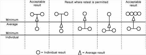
Fig 2.1.8 Acceptance, rejection and retest criteria for the through thickness properties of steels
(2) Fig 2.1.8 shows the three cases where a retest situation is permitted. In these instances three more tensile tests are to be taken from the remaining test sample or remaining steel plates of same piece. The average of all 6 tensile tests is to be greater than the required minimum aver- age with no greater than two results below the minimum average.
(3) In the case of failure after retest, either the lot represented by the piece is rejected or each
piece within the lot is required to be tested.
(4) The test is considered invalid and further replacement test is required if the fracture occurs in the weld or heat affected zone.
![]()
![]()
7. Ultrasonic tests See Guidance
(1) Ultrasonic testing should be carried out on each piece in the final supply condition.
(2) Any requirement for the test procedure and acceptance criteria are left to the discretion of the Society.
However, the probe frequency is to be of 4MHz in general.
8. Marking
![]()
Steels which have satisfactorily complied with the requirements specified in 310. are to have the notation Z25 or Z35 after the material grade mark. (e.g. E H 36 Z25, EH36 Z35)
![]()
311. YP47 Steel Plates
1. Application
(1) This requirements applies to the application of steel plates with thickness of over 50mm and not greater than 100mm and specified yield point of 460 ![]() to longitudinal structural members in the upper deck region of container carriers (such as hatch side coaming, hatch coaming top and the attached longitudinals).
to longitudinal structural members in the upper deck region of container carriers (such as hatch side coaming, hatch coaming top and the attached longitudinals).
(2) For steel plates outside of this thickness range, special consideration is to be given by the Society.
(3) The requirements other than those specified in 311. are applicable to the requirements in 301.
(4) The requirements other than those specified in this instruction are to be in accordance Guidance relating to the Rules specified by the Society.
2. Kinds
The steel plates are classified as specified in Table 2.1.39.
3. Heat treatment
The Heat treatment of steel plates is classified as specified in Table 2.1.39.
4. Mechanical properties
The Mechanical properties of steel plates are classified as specified in Table 2.1.39.
with the
![]()
![]()
![]()
![]()
Table 2.1.39 Conditions of supply, grade and mechanical properties for YP47 steel plates
Grade | Mechanical Properties | Impact test | Supply condition | |||||
Yield Strength ( | Tensile Strength ( | Elongation (%) min | Test Temp. ( ) | Average Impact Energy(J) min. | ||||
L | ||||||||
50< 70 | 70< 85 | 85< 100 | ||||||
EH47-H | min. 460 | 570~720 | 17 | -40 | 53 | 64 | 75 | TMCP* |
Note
* : Other conditions of supply are to be agreed by the Society. | ||||||||
5. Chemical composition
The Chemical composition of steel plates is classified as specified in Table 2.1.40.
![]()
![]()
![]()
![]()
![]()
![]()
![]()
![]()
![]()
![]()
![]()
![]()
Table 2.1.40. Chemical compositions for YP47 steel plates
Chemical composition | *1 | *2 |
As approved by the Society | 0.49% | 0.22% |
Note *1 The carbon equivalent C C Mn Cr Mo V Ni Cu (%) eq 6 5 15 *2 Cold cracking susceptibility P C Si Mn Cu Ni Cr Mo V 5B(%) cm 30 20 20 60 20 15 10 | ||
![]()
6. Selection of test samples
(1) One test sample is to be taken from every similarly heat treated plate as rolled directly from one slab or ingot.
(2) The requirements specified in 301. 6 (4) are to be applied to the selection of the test samples.
7. Selection of test specimens
(1) Tensile test specimens are to comply with the requirements shown in (a) to (c) below:
(a) Tensile test specimens are to be taken according to the requirements specified in 301. 7 (2).
(b) Normally flat tensile test specimens are to be prepared in such a manner as to maintain the rolling scale at least at one side.
(c) When instead a machined round tensile test specimen is used then the axis must be located at a position lying at a distance of t/4 from the surface or as near as possible to this position.
(2) Impact test specimens are to be taken according to the requirements specified in 304. 7 (3).
Surface inspection and verification of dimensions
8. (1) Surface inspection and verification of dimensions are to be in accordance with requirements specified in 301. 8.
(2) If required by the Society the manufacturer is to perform ultrasonic examinations in accordance with an approved standard.
(3) If required by the Society, through thickness tensile tests are to be performed in accordance
with requirements specified in 310.
Retest procedures
9. (1) Where the tensile test from the first test specimen selected fails to meet the requirements, addi- tional tests may be conducted according to the requirements given in 109. 1.
(2) Regarding the impact tests, additional tests are to be carried out according to the requirements given in 109. 2.
10. Marking
![]()
Steels which have satisfactorily complied with the required tests are to be marked with the identi- fication mark in accordance with the requirements in 110.
![]()